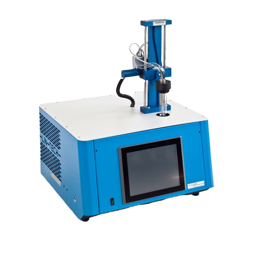
Cloud Pour Point Analyser
CLOUD POINT:
ASTM D2500 – ASTM D5771 – ASTM D5772 – ASTM D5773
DIN 51597
IP 219 – IP 444 – IP 445 – IP 446
ISO 3015
POUR POINT:
ASTM D97 – ASTM D5853 – ASTM D5950
IP 15 – IP 441
ISO 3016
CE marked
Subject
Cloud Point of petroleum products and biodiesel fuels.
Pour Point of petroleum products, crude oils, motor and engine oils, additives, lubricating oils, …
Measuring Cloud and Pour Point Principle
CLOUD POINT
The sample is cooled down according to the methods while the clouds appearance is observed on the silver bottom of the test jar by means of an optical sensor. The measurement is done by reflection on the silver bottom of the test jar via a fast light detector. The signal from light detector is traded by the LabLink software. The dynamic measurement is performed regardless of the sample’s colour.
POUR POINT
According to the methods, the sample is cooled down at a specified rate and, at the prescribed temperature intervals, the mechanical arm of the analyser lifts the test jar from the cooling jacket and tilts it in order to bring it in horizontal position to test the flow of the product. The sample movement is detected by the thermal probes (PT100 detection) placed above the sample surface which react if touched by the cooled sample.
Measuring Cloud and Pour Point Devices
- Cloud: light pulsed emission on I.R spectrum through a coaxial fibber optic
- Pour: platinum resistance PT100 class A
- Pour: mechanical moving arm bringing the test jar in horizontal position
Measuring Temperature Probe
- Platinum resistance PT100 class A
- The Cloud Point PT100 is touching the bottom of the test jar
Measuring Parameters
- Temperatures: in °C
- Measuring range: +80°C … -80°C
- Resolution: 0.06 °C
- Accuracy: ± 0.1 °C
- Repeatability / Reproducibility: as per standards methods or better
Software Features
New LabLink software able to manage up to 6 analytical heads simultaneously (stand alone)
- User friendly interface
- All analytical parameters recorded
- Customizable analysis parameters and methods
- Customizable results report
- Printable graphs and results
- Self-identification of the typology of the analysers connected
The software includes:
ANALYSIS MENU
- Standard method as per ASTM / IP / ISO / EN / DIN… norms of reference:
- internal, with sample pre-heating, for Pour Point only
- external, without sample pre-heating, for Pour Point only
- Optional methods:
- fast bath, to reduce the time of analysis
- T-sample – T-bath (delta T constant)
- cooling rate °C / h
- Audible alarm and displayed messages at the end of the analysis and in case of errors and/or malfunctions
DIAGNOSTIC MENU
- Direct access to all analog, digital, inputs and outputs
- Selectable value displaying: °C / Volt
CALIBRATION MENU
- Automatic calibration of each temperature probe
- Last calibration date referred to each single probe displayed and relative data printable
- Display of calibration diagram
- Insertion of offset values
- Standard and advanced calibration modes
DATA UTILITIES
- Fields for introduction of operator and product name
- Archive viewer for files recall
- All analysis stored in Excel® compatible format
- Storage capacity for more than 60’000 analysis
- LIMS compatible
Integrated Touch Screen Panel PC
- TFT/LCD 12″
- Resolution 1024 × 768, 16.2 M colours
- 2 USB ports for connection to an external printer and/or external PC
- Storage capacity for more than 60’000 analysis
Test Jar
- Same dimensions and volume as described by the standard test methods
- Product level mark
- Small edge on the top in order to fix the glass cell to the analytical head
- Silvered bottom with anti-scratch film protection
Cooling System
Integrated gas CFC free motor compressors:
- Single stage (for temperatures up to -40°C / 1)
- Double stage (for temperatures up to -80°C / 2)
Equipped with an automatic energy power save system. After 15 minutes from the end of the analysis the cooling system goes in stand-by mode.
Safety Devices
- Pressure controller for 1st stage motor compressor
- Pressure controller for 2nd stage motor compressor
- Thermostat for 2nd stage activation
- Thermo-switch for each cooling / heating jacket
- Motor compressors equipped with internal overload devices
Electrical Supply
- 220V ± 15% / 50 to 60 Hz
- 115V ± 15% / 60 Hz
Cord Cable
- 3 conductors flexible cable 2 m (7 feet) length with PVC sheath oil and heat resistant as per CENELEC directives
Ambient Temperature
- Max 32 °C
- H.R. 80%
Partner: LINETRONIC TECHNOPLOGIES SA

